Sean Carron
 Urban Operative Helmet
Urban Operative LED Helmet
Project span
2024 - Present
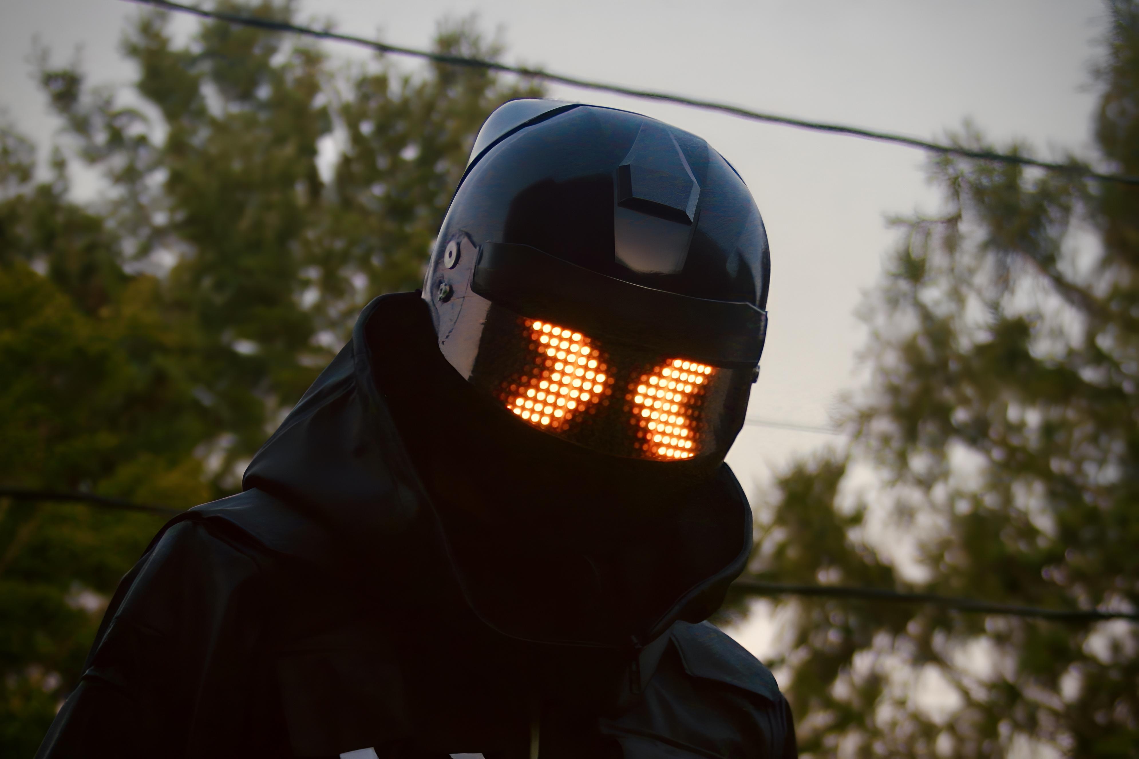
In this project I recreated an animated helmet from a video game called THE FINALS. The helmet was custom 3D modeled in Blender and 3D printed. Electronics were custom made.
The project started in January 2024 after the videogame THE FINALS released. THE FINALS is
an action packed, objective based, competitive first person shooter set in a virtual world
full of uniquely designed “contestants”. One contestant stands out, equipped with a tactical helmet including
a display of animated neon LEDs across the visor. This character is iconic in the world of
THE FINALS. I was inspired to try and make this character's iconic helmet in real life.
Before I could officially launch the project, I needed to create a proof of concept for a few components. By
this I mean I needed to create a prototype or find a feasible solution for some parts of the helmet.
First I needed a solution for the physical chassis of the helmet. Would I buy and modify a motorcycle helmet
or 3D print my own? Next I needed a solution for how I would implement the visor display. I also
wanted other features like full remote control of the helmet and multiple animations. Before I could commit to
a plan of action on the helmet I needed to achieve a working solution for all of these.
I started by buying and returning several different motorcycle helmets from amazon and
testing them for game accuracy and size. I couldn’t find one that was accurate enough to the
game. I also realized I would need to paint over any brand logos and create 3D printed parts to match the game
helmet. This meant that using a real motorcycle helmet wouldn’t actually save me much
labor compared to 3D printing my own. I decided to 3D print a helmet instead of buying one, despite having no
prior 3D printing experience. I bought a Prusa Mini+ 3D printer for the job. The next
problem was acquiring an accurate 3D model of the in game helmet. I originally went to FIVERR to find someone
who could help me create the 3D model. I was unsatisfied with the accuracy of their
model, so I began creating my own model of the helmet. I spent several months in Blender trying to accurately
recreate the helmet model.
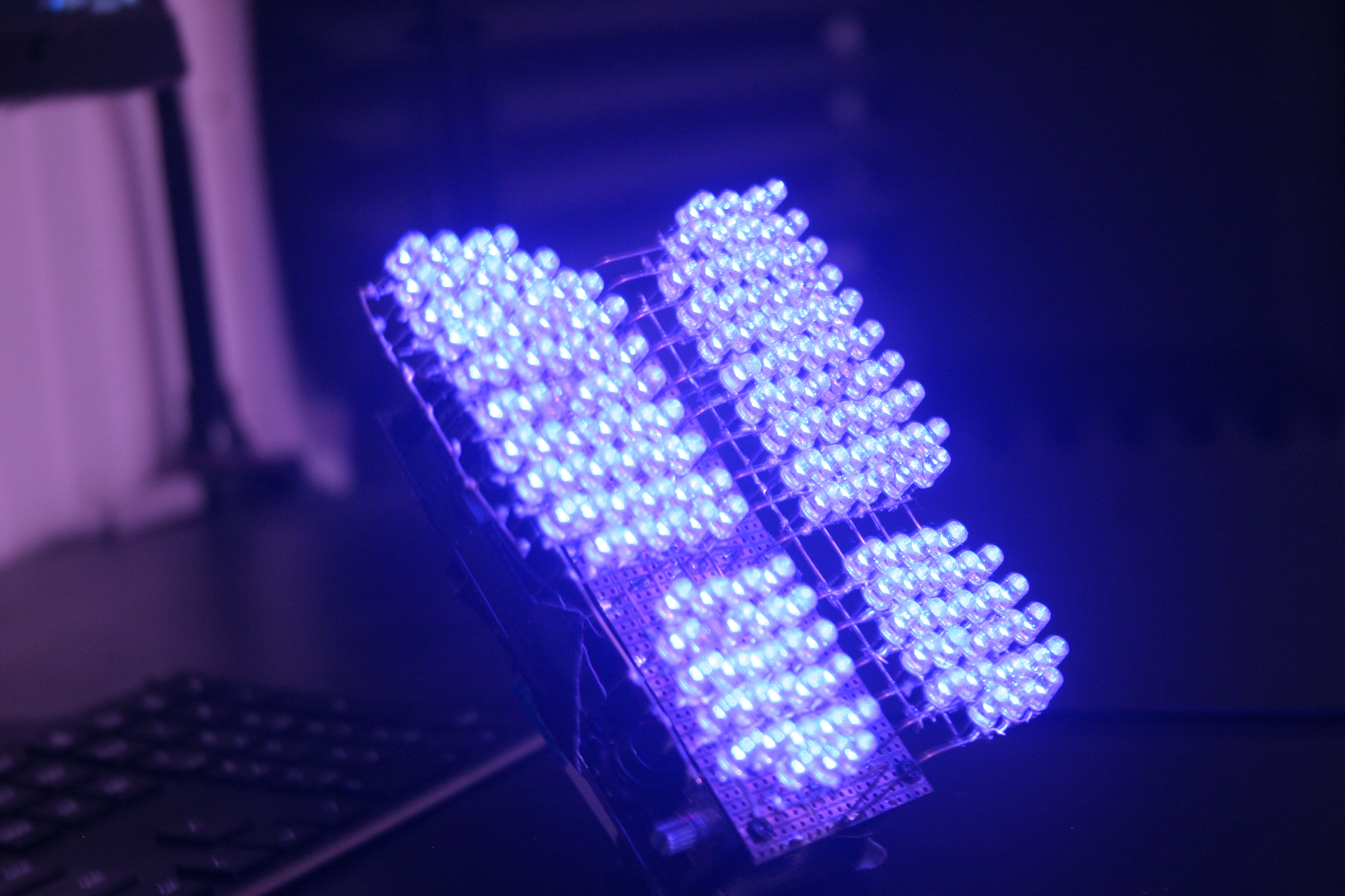
I also needed a prototype for the electronics. How would I create an array of lights behind the visor? I
tested an approach using Neopixel LED strips. These are individually addressable RGB LEDs
evenly spaced in a line on a long bendable strip. But cutting the strip into pieces I was able to daisy chain
the LED strips to create a matrix or grid of LEDs. This LED matrix used only three input
wires: a 5V line, a ground, and a data line. The final matrix is composed of over 300 individual LEDS, each
can be individually controlled using the single data line input. I considered this prototype a success.
I chose a microcontroller, the Particle Photon 2. It had many desirable features such as wifi and bluetooth
connectivity, large memory storage, and a cloud console service included. This meant I could
upload new code to the microcontroller wirelessly. I found an online service named Adafruit IO which allowed
me to create a dashboard on my phone that I could use to communicate with the microcontroller.
To use these services however, the microcontroller needed to be connected to wifi. Through testing I found I
was able to connect the microcontroller to my phone's mobile hotspot. This would allow me to
communicate with the helmet wirelessly anywhere I had cell service.
There was still a problem. There is only one code library I could find for connecting to the Adafruit IO
server from the Particle Photon 2. This library was outdated and my code wouldn’t work. I analyzed
the code from the library and compared it to the updated documentation for connecting to Adafruit IO. Through
close analysis, I found the commands used in the library that were deprecated. I copied the
code from the library into my own project where I was able to make my own edits to it. I created an updated
version of the library with new commands compatible with the current version of Adafruit IO.
This was a success, I was able to send and receive messages from the helmet using an Adafruit IO dashboard on
my phone.
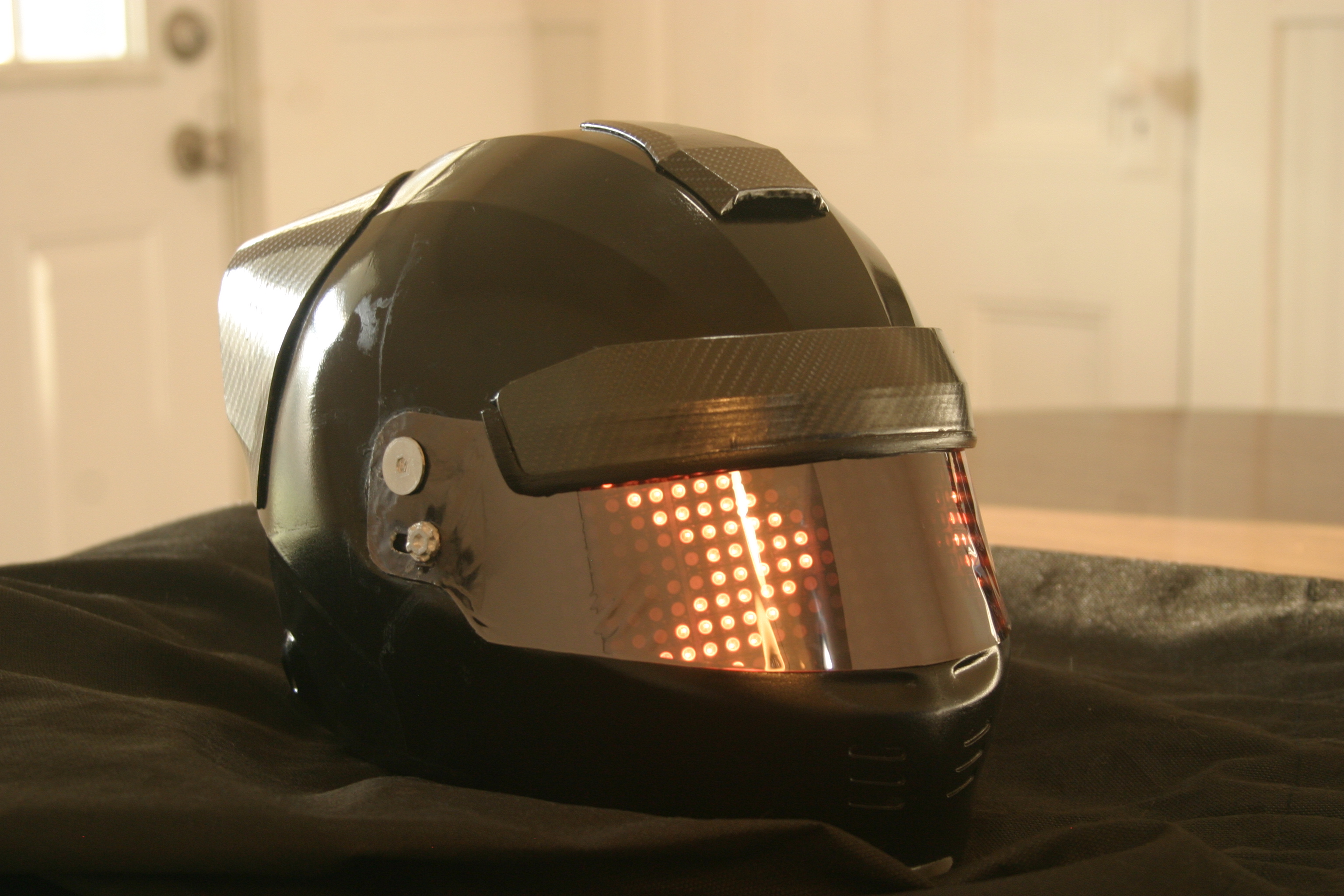
LED Matrix first prototype
Using Adafruit IO with the finished helmet
I designed the helmet 3D model such that all of the electronics can mount inside. This meant
that the electronics had to be completely finished before I could complete the model and begin
printing the helmet. I used two 11v lipo batteries as the power source. I used a 5V linear regulator to step
the voltage down and power the microcontroller. The LED matrix required a different solution.
Over 300 LEDs on full brightness pulled over 3 amps. I used a buck converter to step down the voltage from the
batteries while stepping up the current. I used this to supply power to the LED matrix. The buck
converter has an onboard potentiometer which sets the output voltage. This is a problem. For one,
potentiometers can drift from their set value over time. Also, the potentiometer has to be turned manually
with
a screwdriver, which is inconvenient. The neopixel LEDs require a steady 5V to function correctly. I found
through testing that powering on all LEDs to full brightness draws so much current that the
output voltage of the buck converter drops below 4V from 5V. At around 3.5V the neopixels began to
malfunction, displaying random colors. I created a unique solution to this problem. I desoldered the
onboard potentiometer and added a digital potentiometer IC to my circuit. This is a chip that emulates a
potentiometer, while being controllable from the microcontroller’s digital IO pins. I used this
in combination with a simple resistor protection circuit to protect the IC and the microcontroller from high
voltage spikes coming from the buck converter. I can now control the output voltage of the
buck converter through my code.
The microcontroller and other components were soldered onto a prototyping circuit board. Once finished, I used
a dremel tool to cut them to size. With the electronics cut out, I could measure them with
a caliper and design a mounting solution to mount them to the inside of the helmet. I could finally begin 3D
printing the helmet. Indentations were made to perfectly fit the circuit boards and batteries.
I tried an idea using hex nuts and screws to mount the circuit boards. I created indents in the helmet to glue
hex nuts, laid behind the cut-out for each circuit board. This provided threading I could
use to screw in screws which would hold down the boards. The batteries friction-fit into perfectly modeled
indents in the back of the helmet. I designed and 3D printed a cover which covered all of the
electronics, separating them from the user's head. A cable with a connector plugs into the LED matrix which
would mount across the visor.
 LED Matrix Butterfly
LED Matrix Butterfly
Project span
2023
In this project I created a custom LED sculpture using individual 5mm LEDs powered by Arduino.
 POV RC Airplane
Custom RC Airplane with live POV Camera
Project span
2019 - 2020
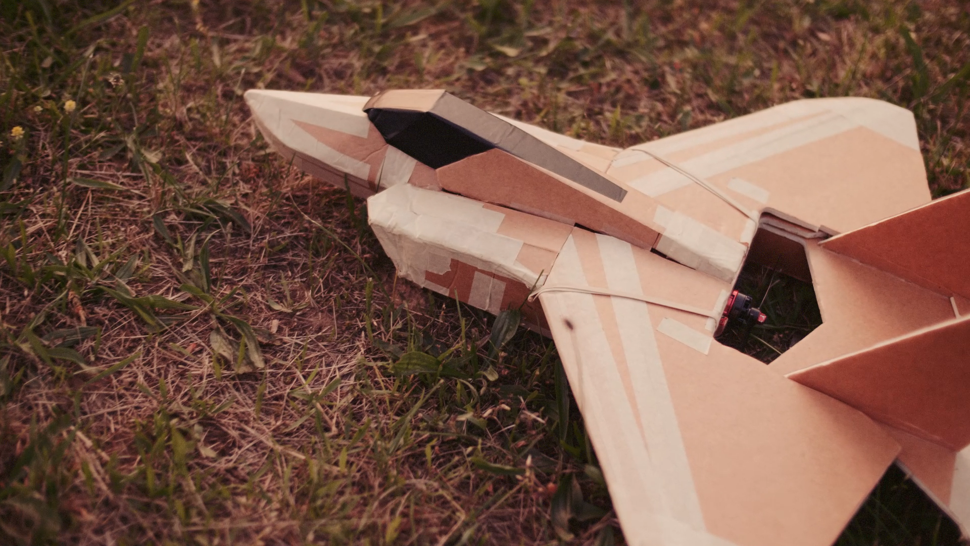
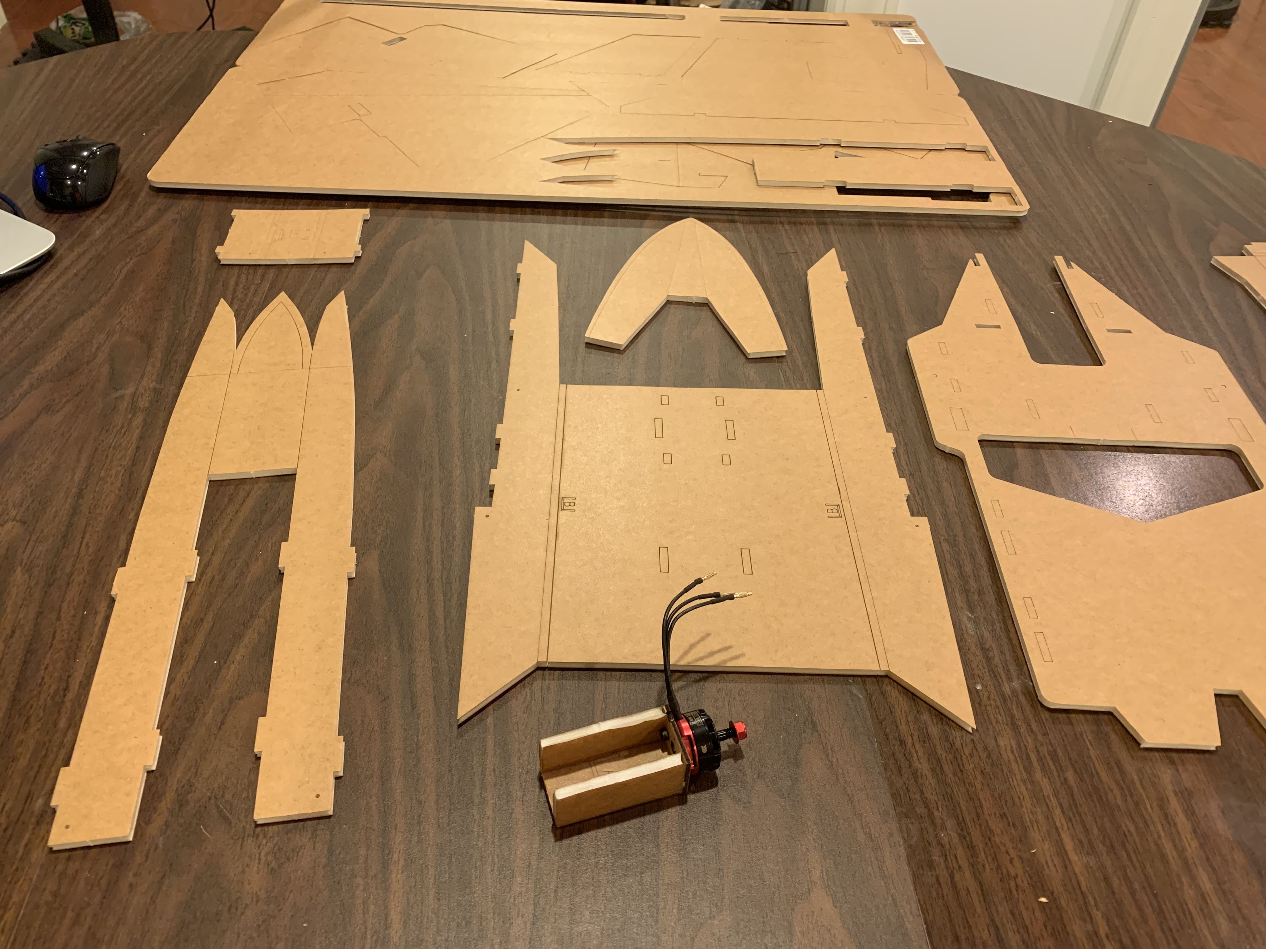
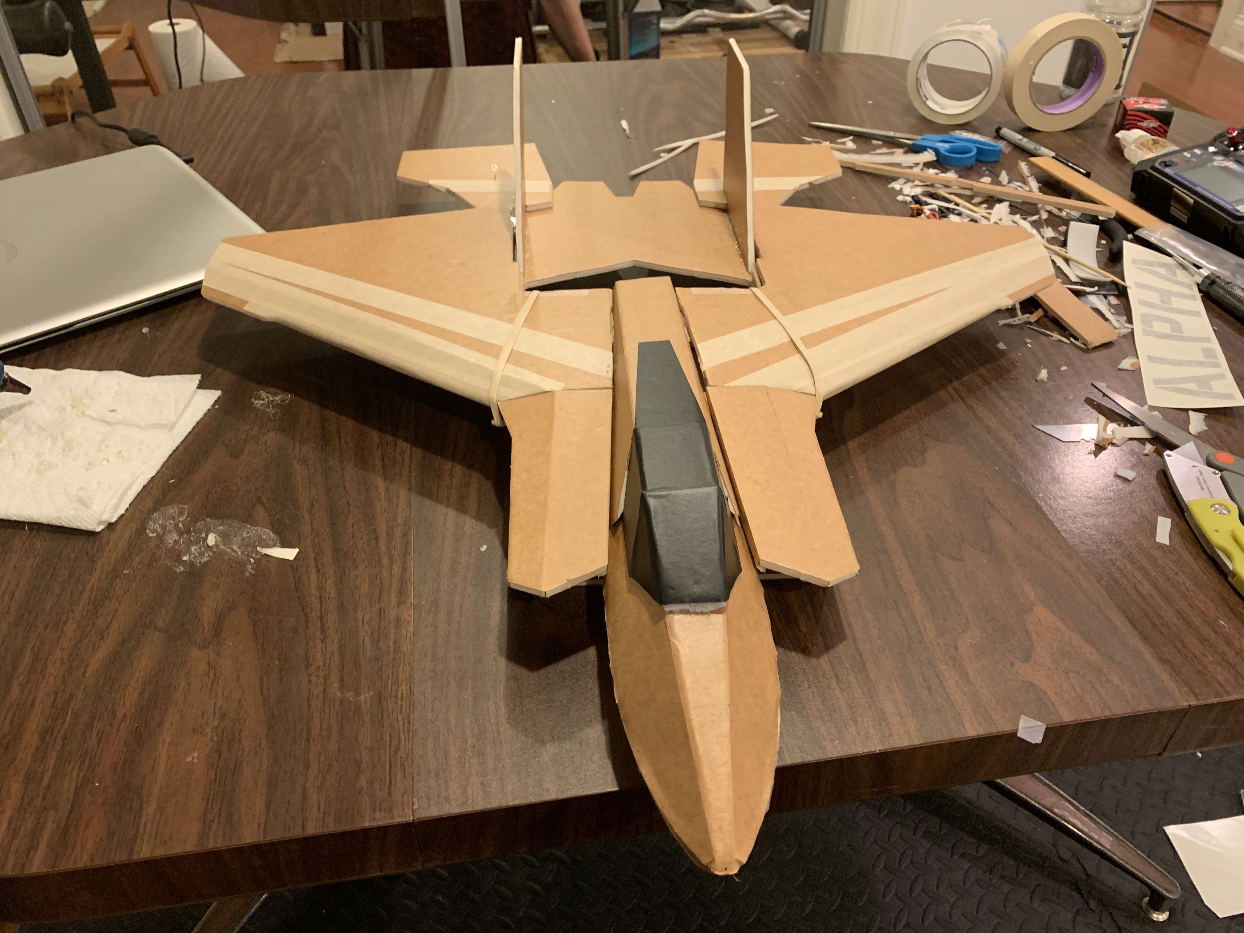
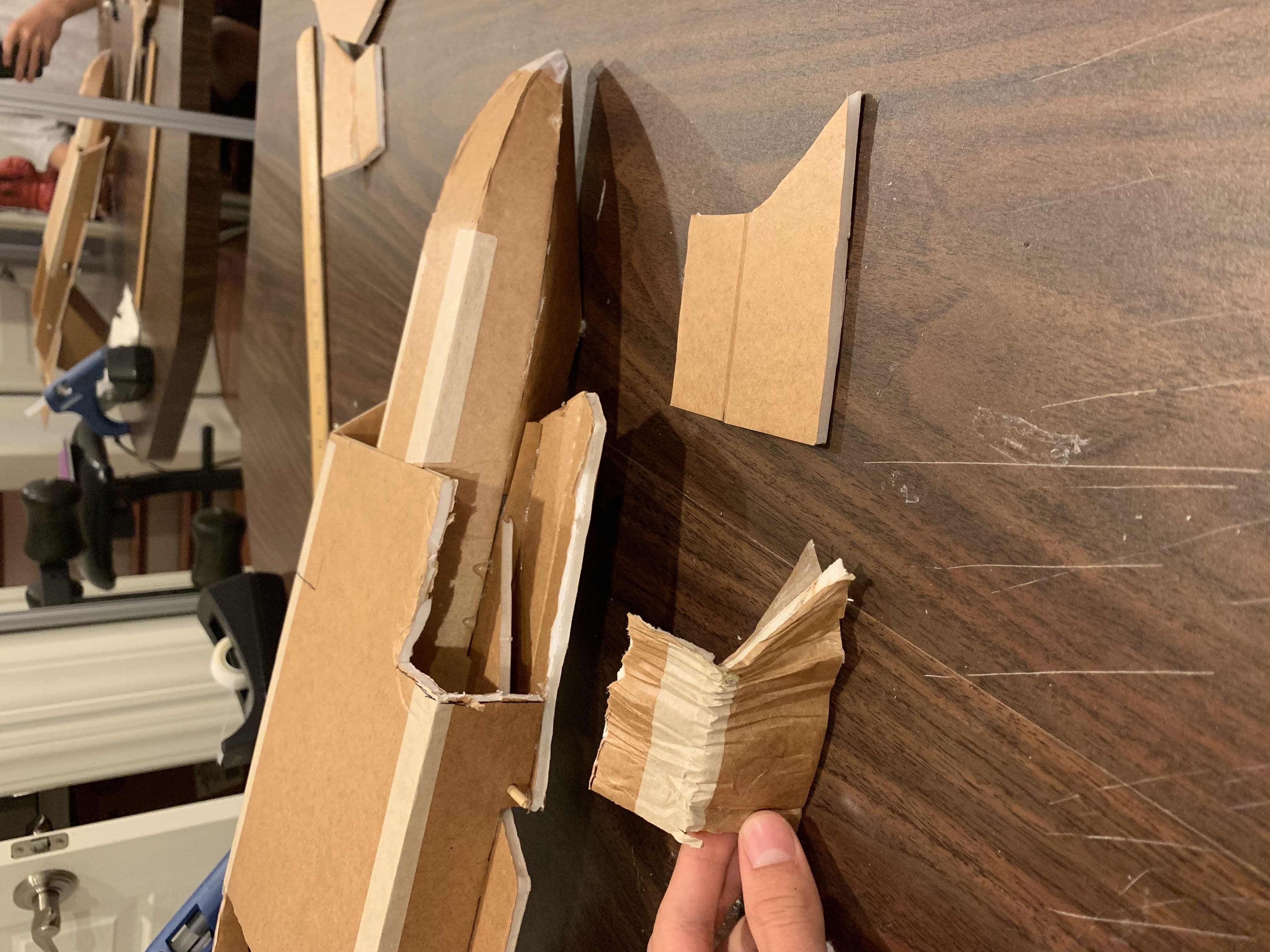
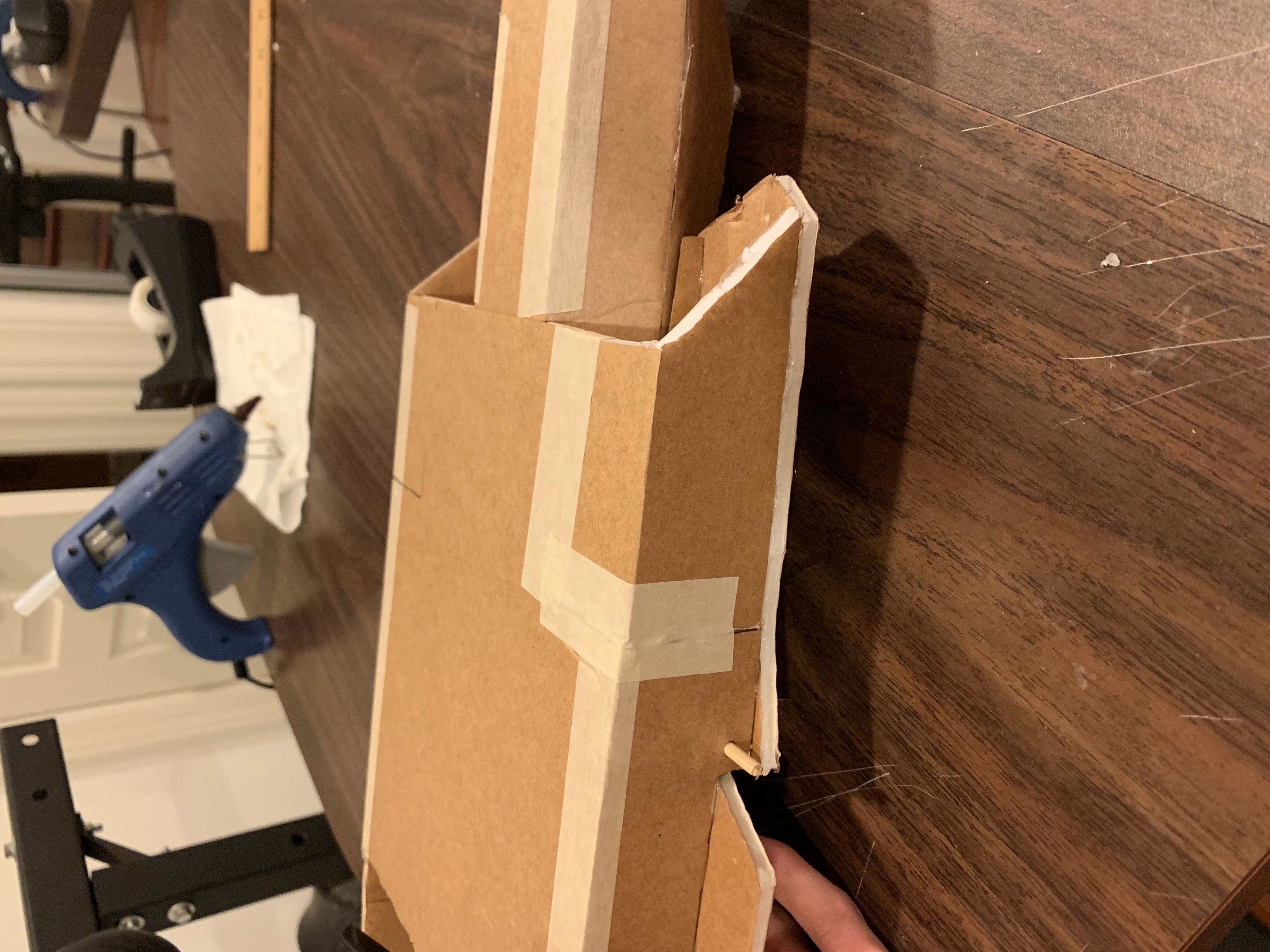
This project began in summer 2019 where I built a remote control fixed-wing airplane. The aircraft is built from a kit containing lazer-cut foamboard pieces.
I modified the aircraft to include a live FPV camera and video transmitter. The camera is mounted underneath the nose of the aircraft and transmits a live video feed to a pair of FPV goggles.
Aircraft Construction Kit: store.flitetest.com/ft-alpha-mkr2
FPV Goggles: fatshark.com/product-page/recon
Controller Transmitter: DTXMX Flysky FS-i6 RC Transmitter and Receiver
This project was difficult but fun. Although the project came as part of a kit, it still
required lots of craftmanship and careful construction skills.
This project was difficult but fun. Although the project came as part of a kit, it still required lots of
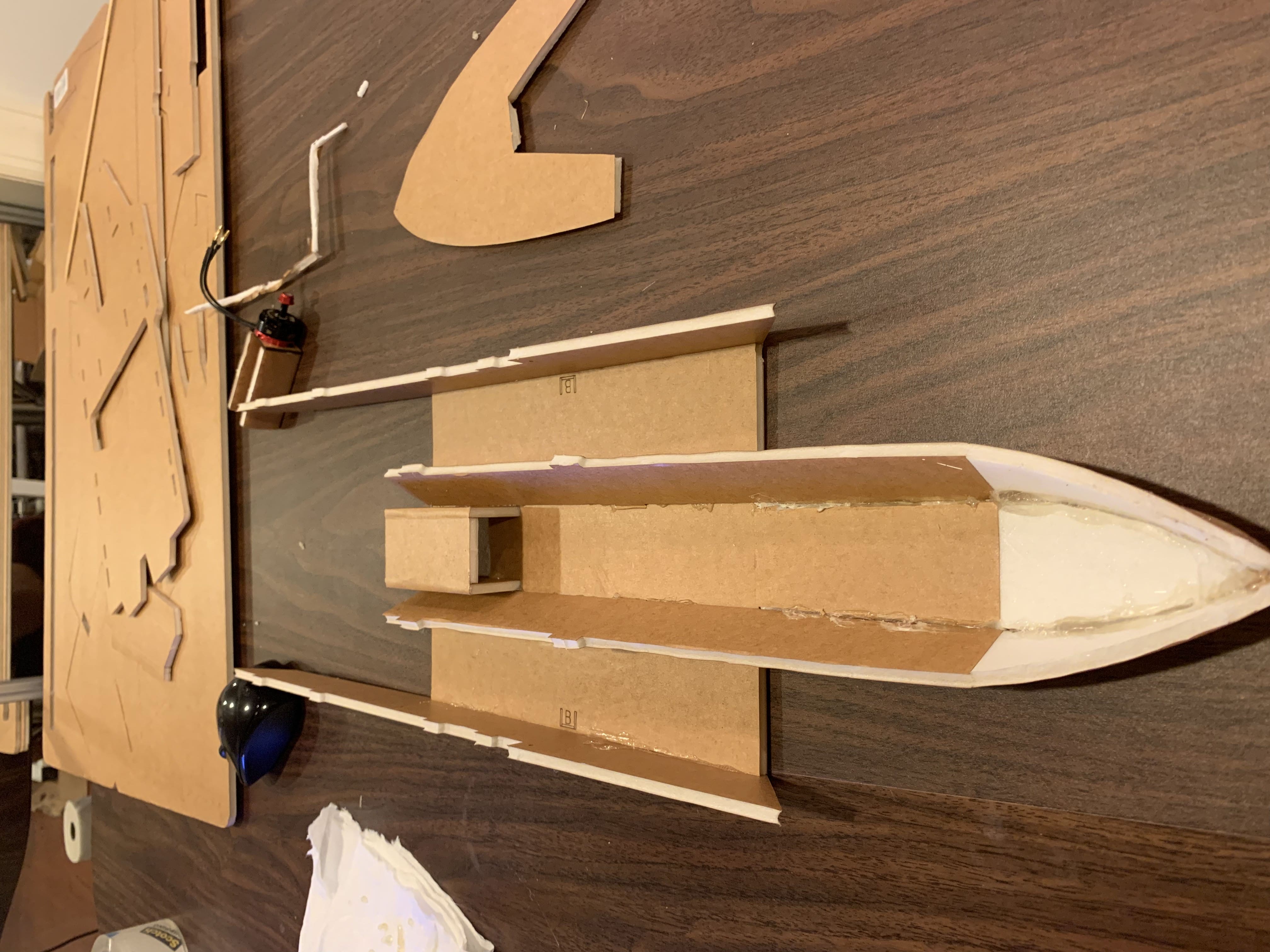
craftsmanship and careful construction skills.The plane is made of a foamboard material.
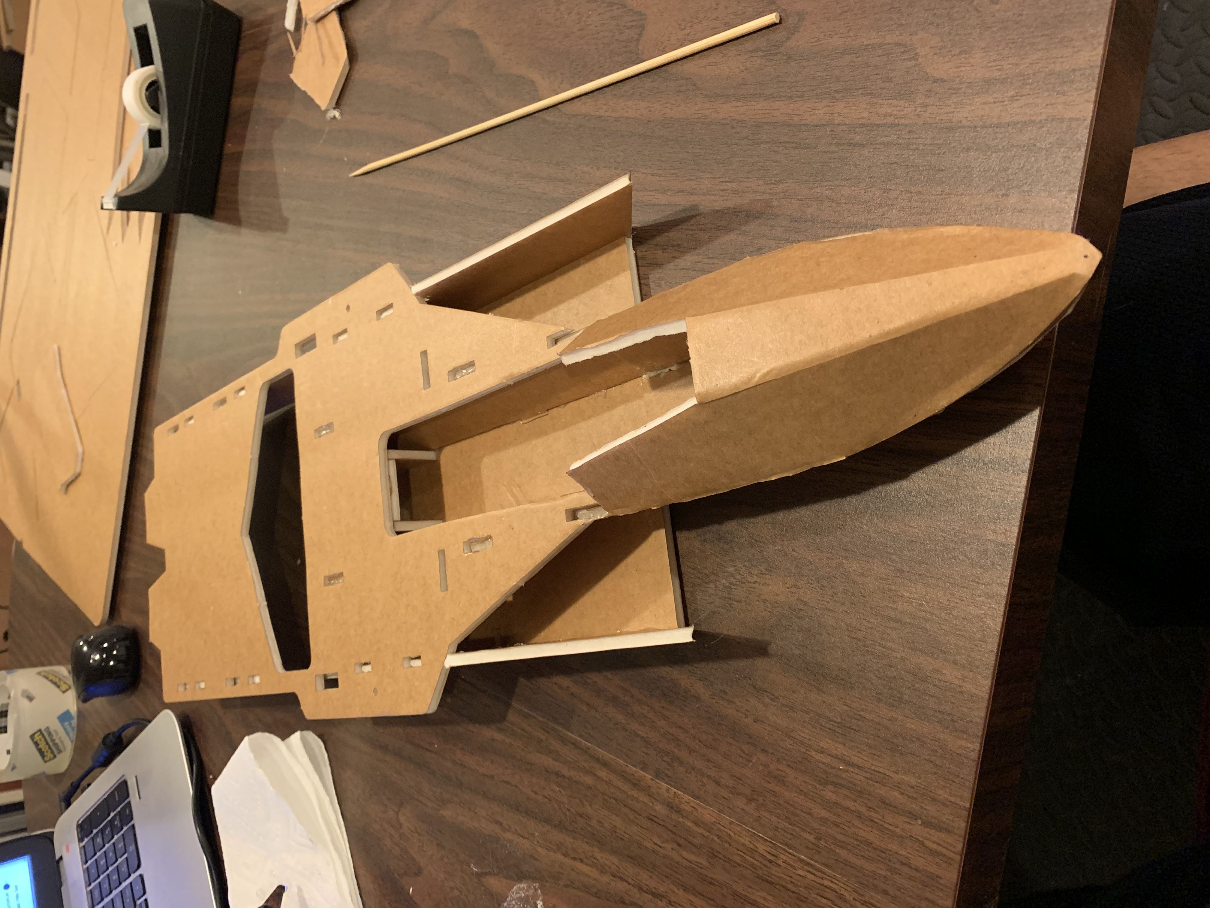
Many pieces had to be cut to exact shapes or have their edges cut at angles so that pieces mate correctly. I
used an exacto knife or razor. Hot glue was used to connect pieces and had to be applied
quickly and confidently. The electronics were mostly simple using the optional “power pack” kit on the product
website. The plane uses one RS2205 brushless radial motor with max thrust 1024g.
The plane uses one lipo battery at 850mAh 11.1V 45C. I later upgraded to a higher capacity battery. The power
pack also included two 5g servos which controlled the elevons and an electric speed
controller to control the motor.
The plane has only two controllable control surfaces at the rear. These flaps act as both the ailerons to
control roll and elevators to control pitch. They are therefore called elevons. To steer the
plane I use a “bank and yank” technique. This is where I bank the plane to one side and then raise the elevons
to lift the nose, therefore turning in that direction.
The plane is controlled using a 6-channel 2.4GHz radio transmitter. The transmitter has two joysticks and
several switches. One joystick controls motor throttle, the other controls pitch
and roll. I practiced flying in a large open field with no obstacles. I had to learn how to judge altitude and
speed by eye. I crashed the plane many times while learning.
Later I bought a small drone camera with a wireless radio transmitter online. I spliced it directly into the
plane's 5v line and it works. I taped the antenna underneath the body of the plane and the camera mounted
against the “cockpit” of the plane. I bought FPV goggles online which pick up the video signal. Flying in
first
person is an awesome but terrifying experience. The FOV is poor, meaning I can hit obstacles like trees during
sharp turns. The range for video and controls is decent, mostly within line of sight I can maintain
connection.
The plane is repairable after crashes. First I cut out the damaged sections. Then I cut a replacement section from extra foamboard. I use hot glue to attach the new piece and tape over the seams.
 The Behemoth
Minecraft Redstone 32 Screen Display
Project span
2013 - 2014
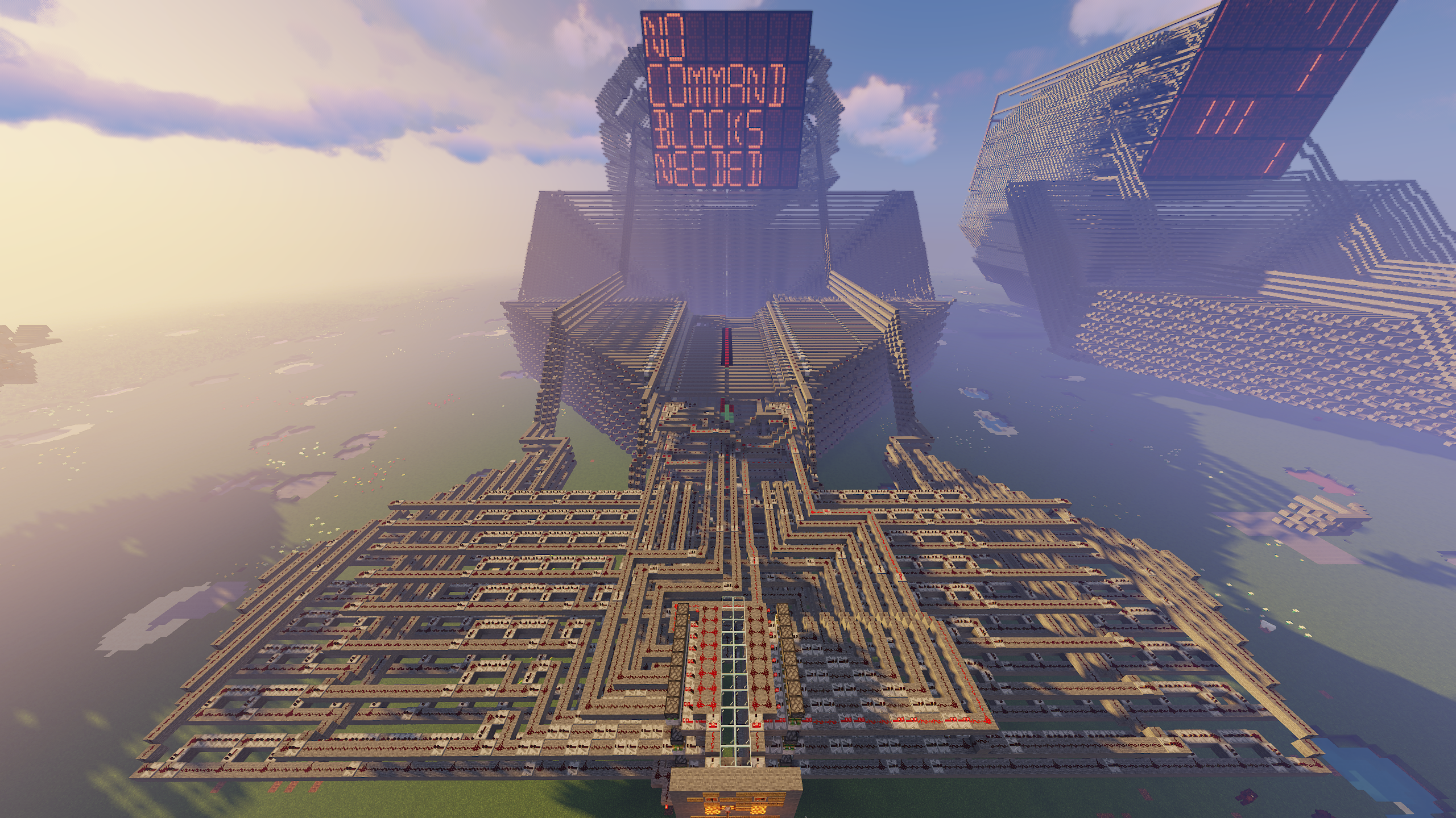
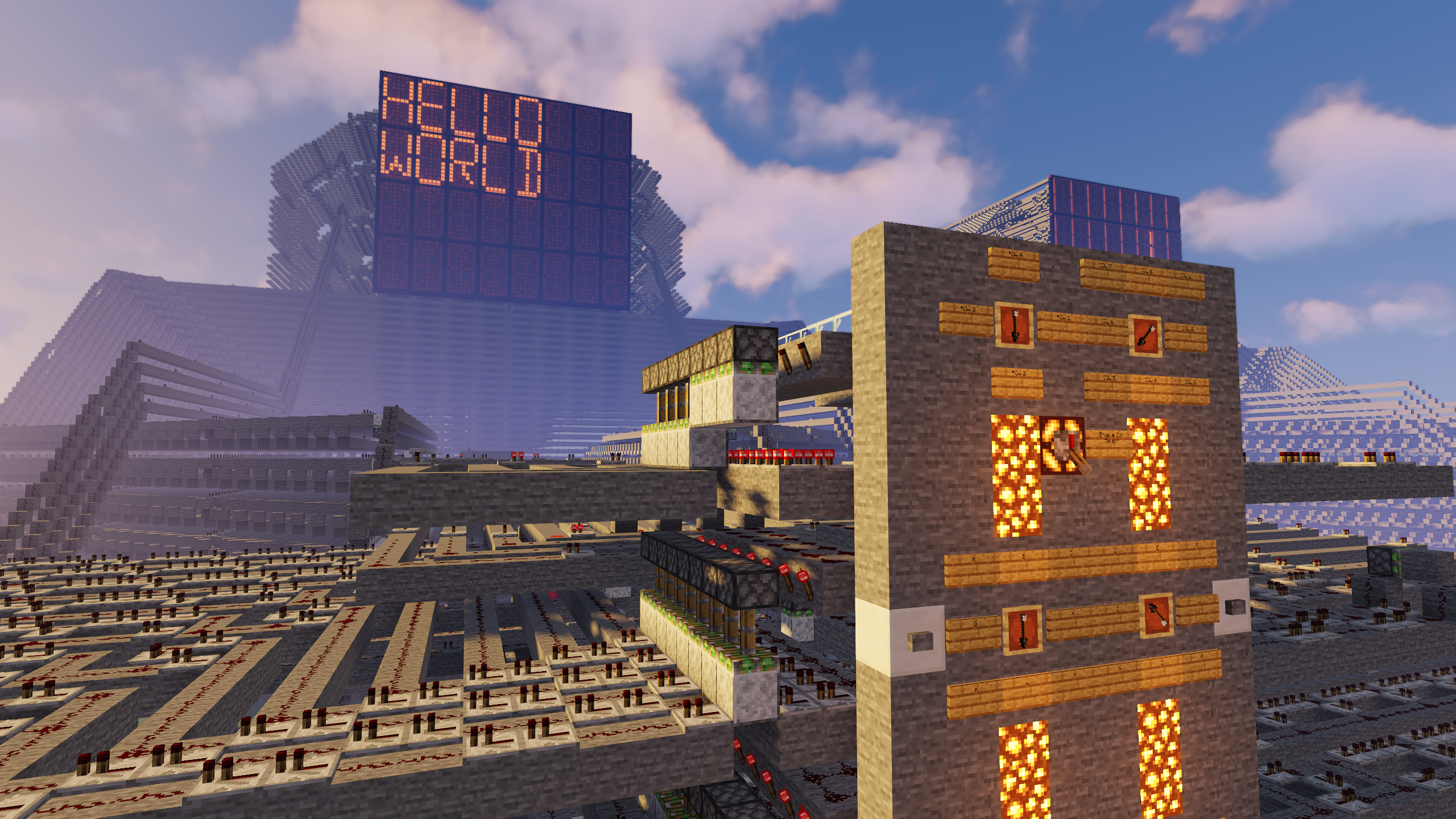
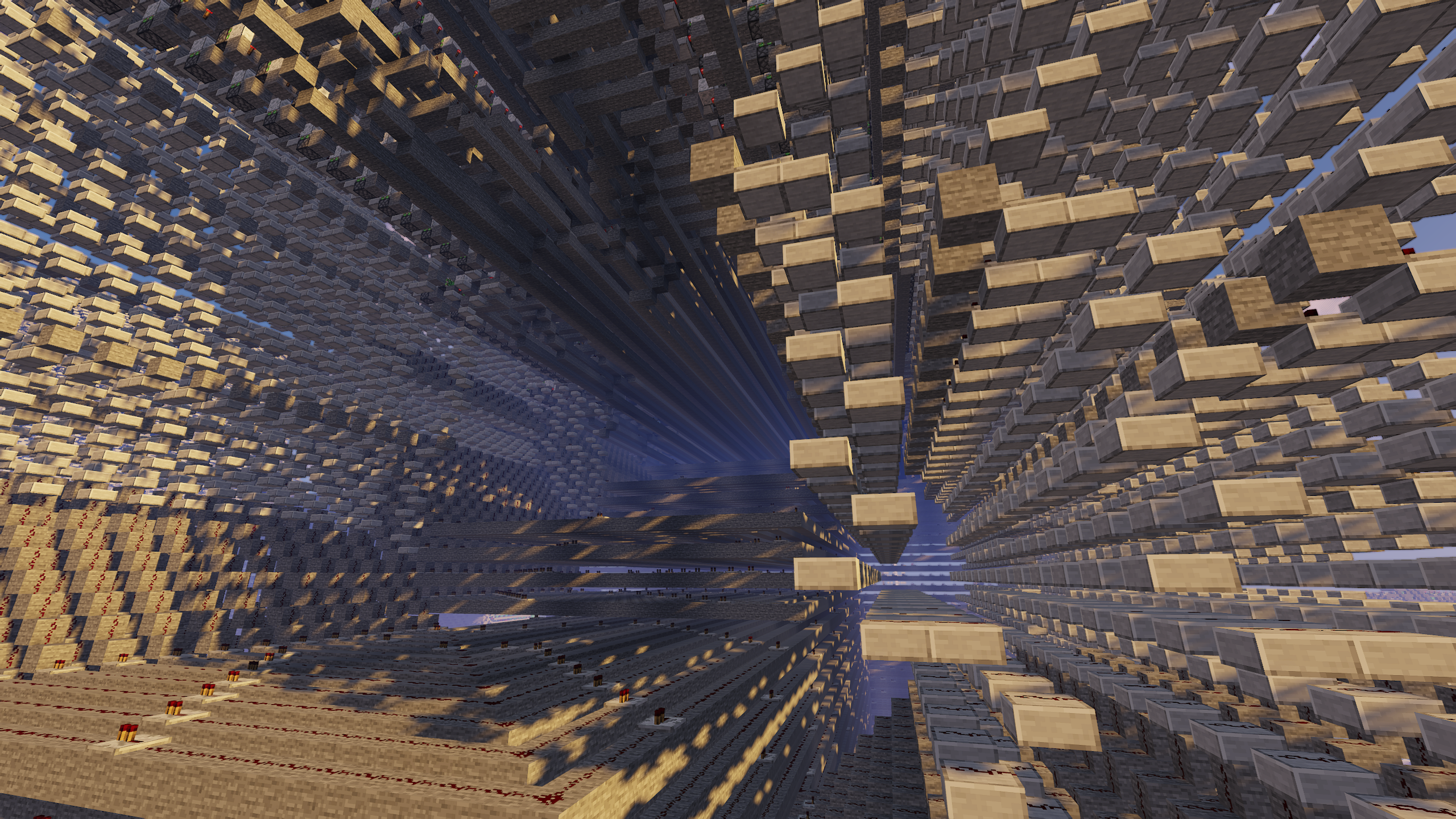
At 13 years of age I created what is to this day one of my proudest achievements. Nicknamed
“The Behemoth”, this colossal machine gives the user the ability to type with an in-game keyboard
onto an in-game screen. For those unfamiliar, this project was created entirely in a videogame called
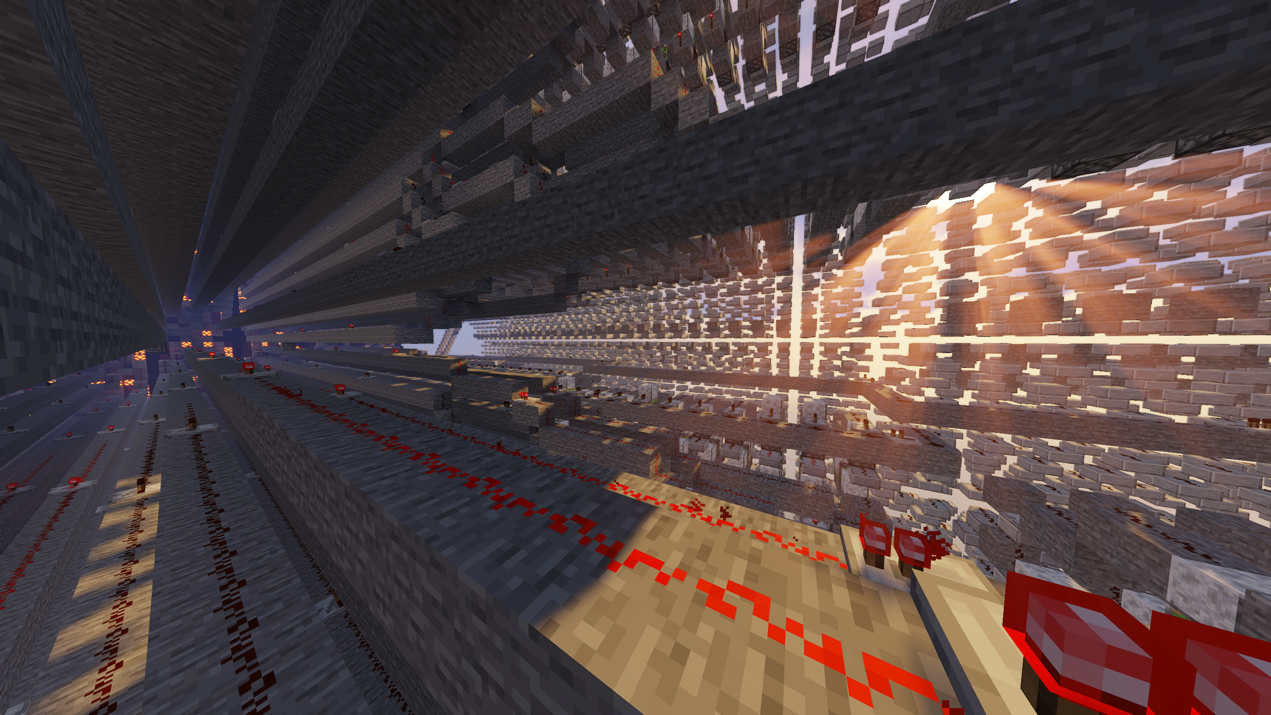
Minecraft. Minecraft has a complex electrical system called “redstone”. Redstone includes user inputs such
as buttons, levers, and dials, as well as outputs like controllable light-up blocks and extending pistons.
The majority of the structure you see is comprised of redstone wires which carry a signal from one component to another.
It’s also possible to create logic gates using redstone. With these simple components I was able to
conceive and construct an enormous and unbelievably complex machine.
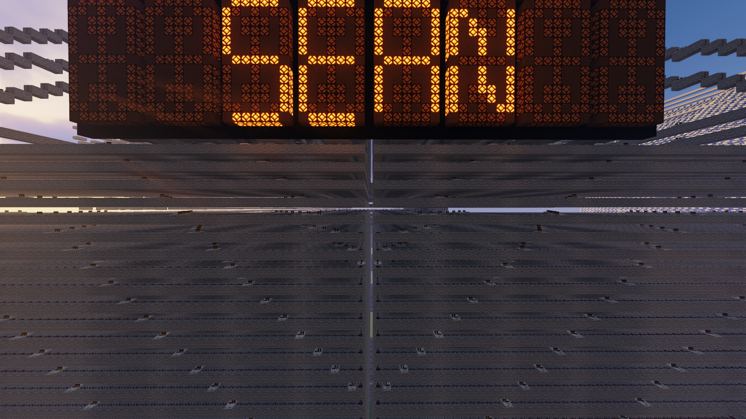
While not technically a computer, this machine controls a giant 32-unit display which can be controlled and
written to by the user. This allows the user to type full sentences onto the screen using an in-game
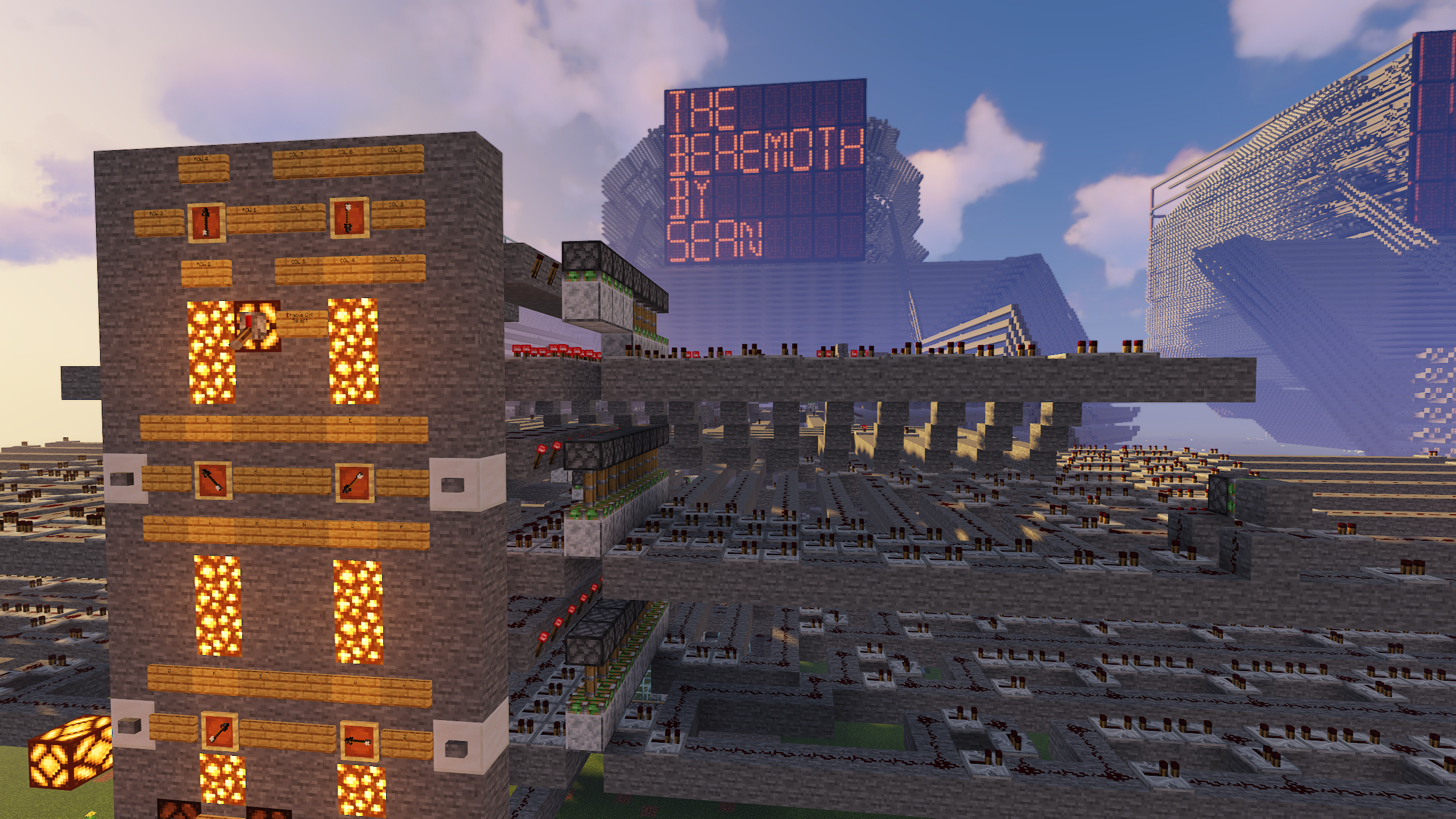
custom alphabet input system. Each display unit is a custom designed 13-segment display. Users interact with
the machine using turnable dials which point to the selected operation, as well as buttons to submit
the operation of their choice. Individual displays can be selected, written to, or cleared. The user can clear
an entire row, or the entire board with a button push.
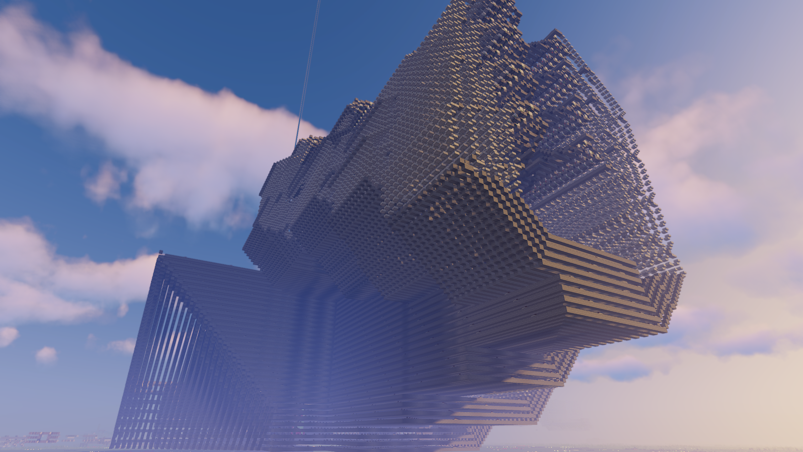
Massive, intimidating, old, and slow, The Behemoth earns its name well. Using it requires careful patience. It can
take about 5 - 20 seconds to display a letter after the user input. To function correctly, the machine
requires the user to increase their render distance to at least 24 chunks. The machine is so big that standing
too far from the center of it during operation causes malfunctions as some parts of it aren’t loaded by the game. Some
internal mechanisms using pistons are actually prone to breaking if operated incorrectly. Having received only
minor updates to maintain functionality through over a decade of Minecraft updates, The Behemoth
continues to impress. Constructed at an age prior to me receiving much technical education, the machine is
undeniably inefficient. But it works.
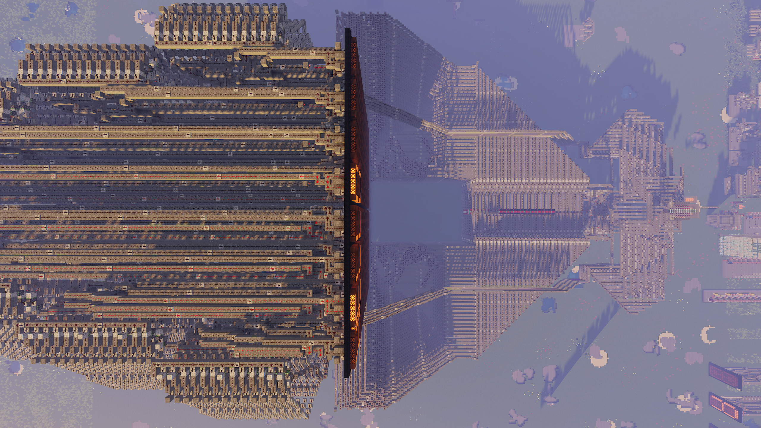
Other creations include a scrolling feed.